EL E 385 Test 1 Fall 2003
Closed Book: No references allowed.
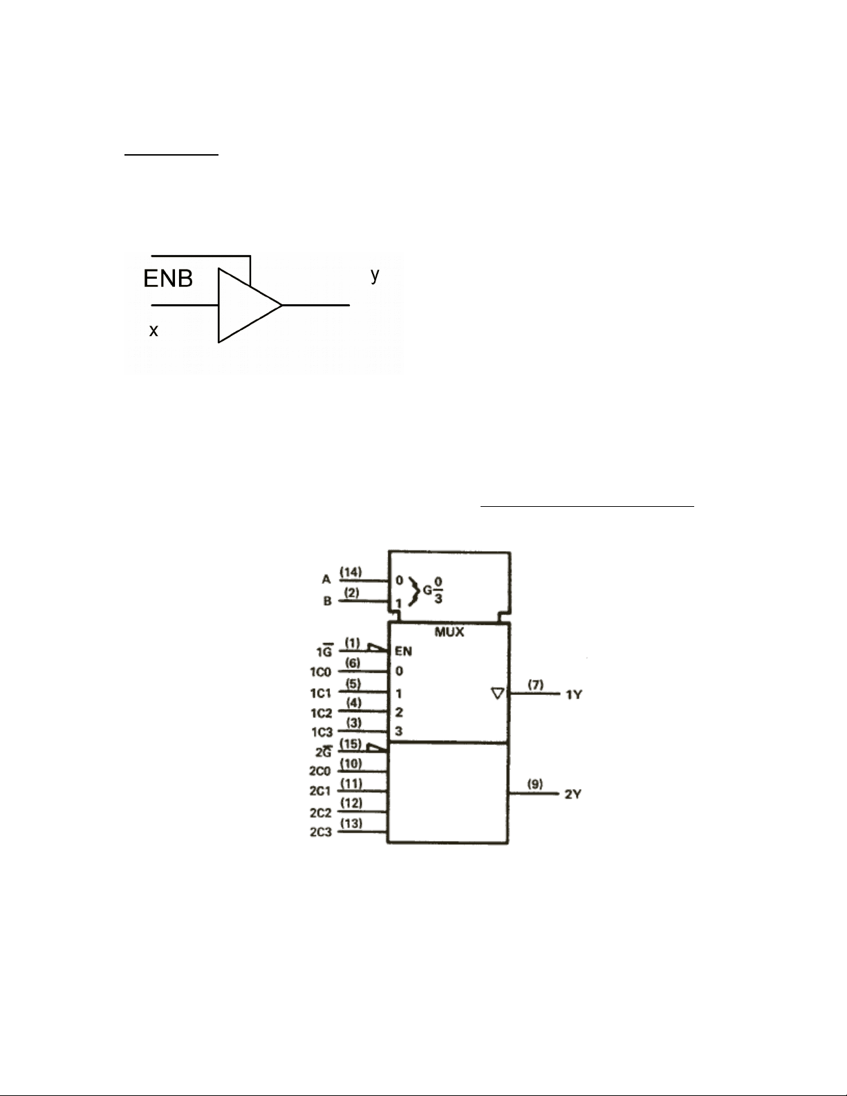
1. (10 points)
Explain the logical operation of the symbol drawn below. That is, give the
output, y, in terms of the inputs x and ENB.
2. (15 points)
a) Shown below is the symbol for a Dual 4-line to 1-line data
selector/multiplexer with 3-state outputs. Show the connections that will make
this an 8-line to 1-line data selector/multiplexer. Label the inputs and outputs.
b) Circle the input signal line that would be selected when the address is 1102.
3. (15 points)
Use the data sheet for the Dual 4-line to 1-line data selector/multiplexer
with 3-state outputs to find the fan-out when one SN74LS253 drives other
SN74LS253's. Show your work.