EE/CS 120A
Homework 3
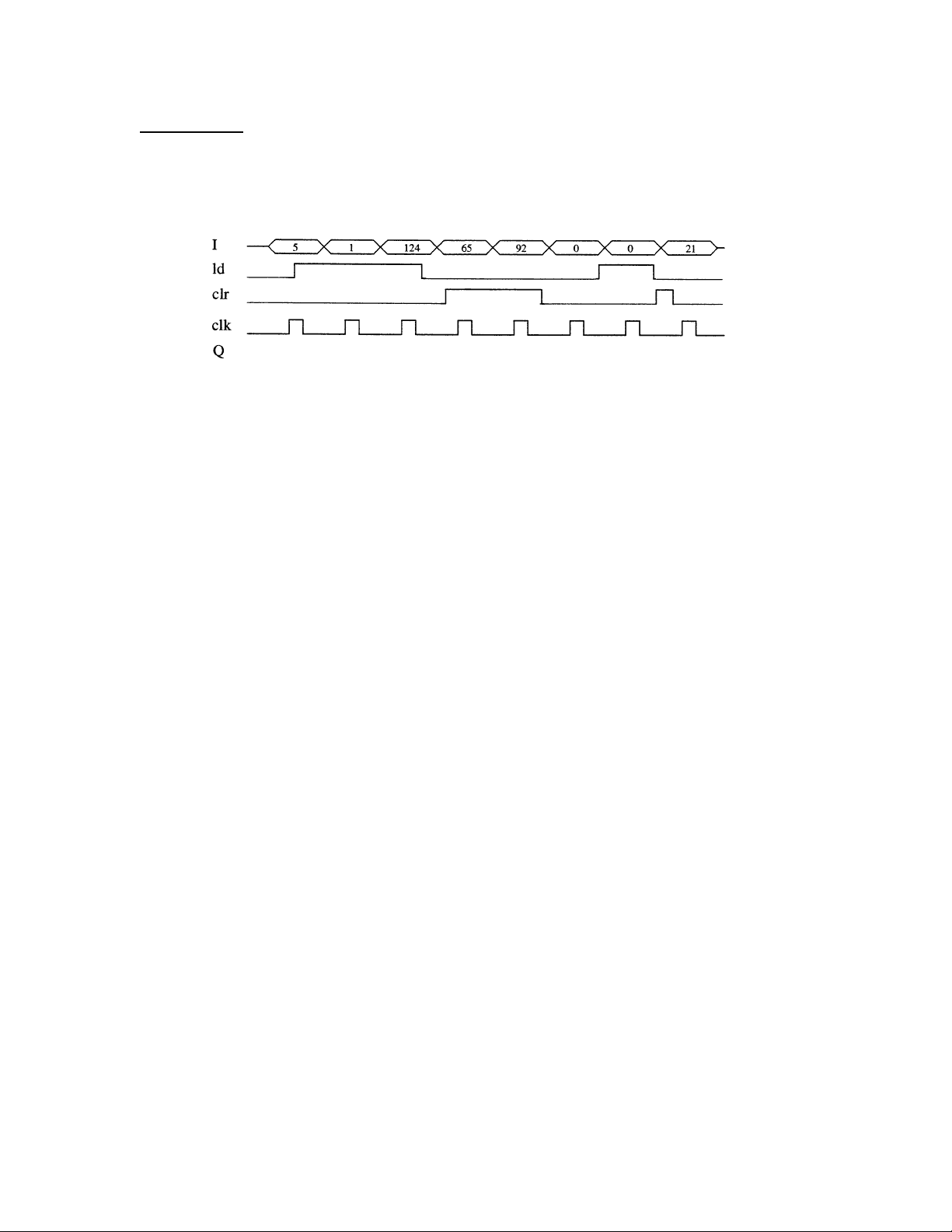
4.2. (Section 4.2) Trace the behavior of an 8-bit parallel load register with input I, output
Q, load control input ld, and clear input clr by completing the following timing diagram.
4.3. (Section 4.2) (Component Design) Design a 4-bit register with 2 control inputs s1
and s0, 4 data inputs I3, I2, I1 and I0, and 4 data outputs Q3, Q2, Q1 and Q0. When
s1s0 = 00, the register maintains its value. When s1s0 = 01, the register loads I3…I0.
When s1s0 = 10, the register clears itself to 0000. When s1s0 = 11, the register
complements itself, so for example 0000 would become 1111, and 1010 would become
0101.
4.10. (Section 4.3) (Component Design) Design a 10-bit carry-ripple adder using 4-bit
carry-ripple adders.
4.11. (Section 4.3) (Component Design) Design an adder that computes the sum of three
8-bit numbers.
4.17. (Section 4.4) (Component Use) Design a circuit that outputs the average of four 8-
bit inputs (which are not in two’s complement form).
4.34. (Section 4.6) (Component Design) Design a 4-bit up-counter that has two control
inputs: cnt enables counting up, while clear synchronously resets the counter to all 0s.
4.35. (Section 4.6) (Component Design) Design a 4-bit down-counter that has three
control inputs: cnt enables counting up, clear synchronously resets the counter to all 0s,
and set synchronously sets the counter to all 1s.
4.45. (Section 4.8) Convert the following two’s complement binary numbers to decimal
numbers:
a. 11100000
b. 01111111
1