Download Single and Double Slit Diffraction and Interference Experiments and more Lab Reports Physics in PDF only on Docsity!
Phys 132L Spring 2009
Laboratory 14: Diffraction and Interference
A characteristic of waves is the ability of a single wave to split into two or more waves and for these to subsequently interfere with each other. In such processes it is possible for interfering waves to reinforce or to cancel each other out, resulting in interference and diffraction patterns. Producing such interference or diffraction patterns for a physical system is a strong indicator that the system is properly described in terms of waves. The aim of this laboratory is to investigate the production of such patterns using light.
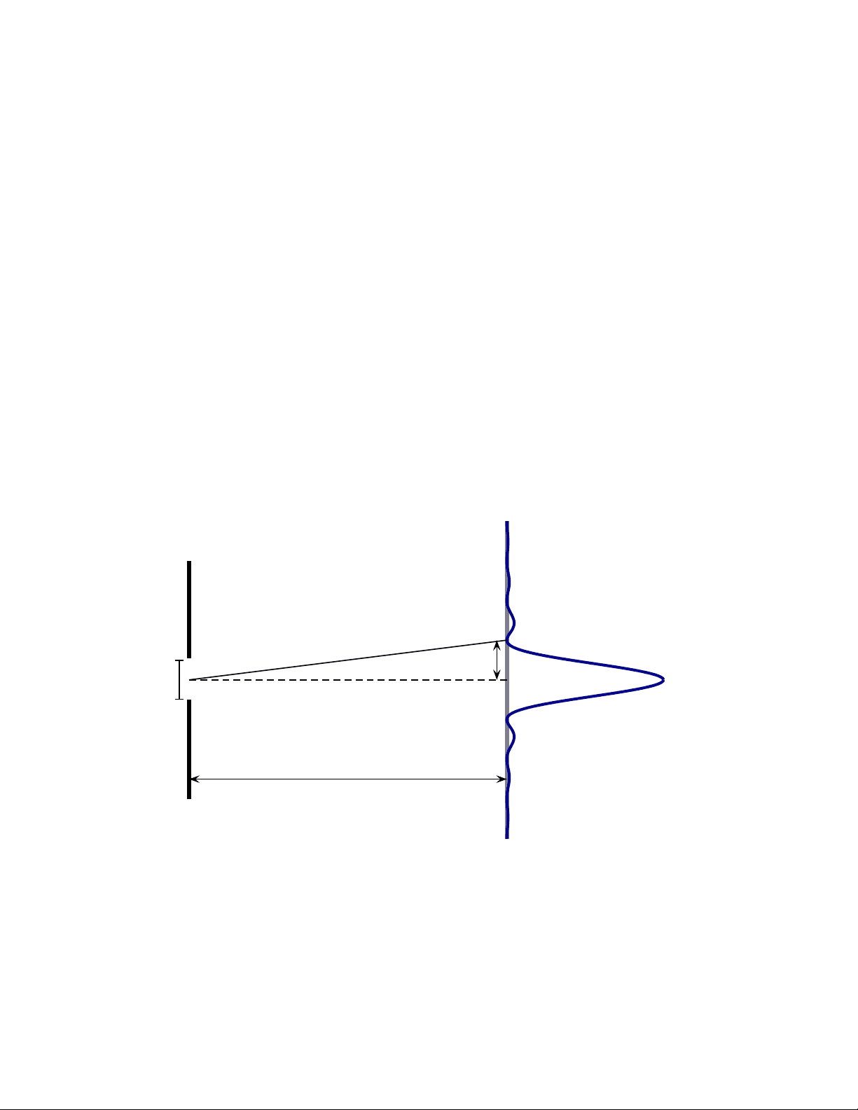
1 Single Slit Diffraction. Light that is incident on a single slit splits into multiple waves, one emanating from each point in the slit opening. These waves interfere to produce a characteristic diffrac- tion pattern beyond the slit. The intensity of the light is plotted in the figure below and this indicates a pattern of bright and dark spots.
a
Single slit
L
m = 2
m = 1
m = − 1
m = − 2
y 1 θ
Analyzing the interference between the multiple waves indicates that dark spots appear at angles θ which satisfy a sin θ = mλ (1)
where a is the slit’s width, θ the angle from the normal to the bright spot, λ the wavelength of the light and m =... , − 2 , − 1 , 1 , 2 ,... is an integer. The integer is referred to as the order of the minimum.
Denote the distance from the central peak to the mth minimum by ym. It can be shown that, to a good approximation,
ym = m
λL a
where L is the distance from the screen to the slit. The aim of this experiment is to investigate single slit diffraction patterns and to verify Eq. (2).
a) Set up the PASCO Single Slit Disk and measure the distance from the slit to the screen. b) Select the single slit for which the slit width is a = 0.04 mm, turn on the laser and align the slit and laser so that the light is incident upon the slit. Place a sheet of paper on the screen and sketch the diffraction pattern as accurately as possible. Measure the distance between the two first order minima (m = 1 and m = −1 the figure above), enter the results into Table 1 and use these to calculate the distance from the central maximum to the first dark spot, y 1. Repeat this for the second order minima (m = 2 and m = −2 the figure above) and, if possible, for the third order minima.
Distance between dark spots Measured^ ym^ Calculated^ ym^
Percent difference
First order (m = ±1)
Second order (m = ±2)
Third order (m = ±3)
Table 1: Diffraction for a single slit.
c) Calculate ym for each case and determine the percent difference between this and the measured value. Enter the results into Table 1. d) Sketch, to scale, the diffraction patterns produced by slits of width a = 0.02 mm and a = 0.08 mm. Describe whether the distance to the first order minima increases, decreases or stays constant as the slit width increases.
2 Double Slit Interference and Diffraction. When light is incident on a double slit barrier, a light wave propagates from each slit. The two light waves interfere and produce bright spots when
d sin θ = mλ (3)
Slit width Slit separation Measured ∆y Calculated ∆y Percent difference
0 .04 mm 0 .25 mm
0 .04 mm 0 .50 mm
0 .04 mm 0 .125 mm
Table 2: Separation between diffraction minima for a double slit.
d) Sketch the diffraction patterns produced by 3, 4, and 5 slits.
3 Conclusion
What is your main conclusion from this lab?
4 Exercises
a) Suppose that light is incident on a double slit for which the slit separation is d = 0 .125 mm. Dark spots appear in order at the following angles: θ = 0. 14 ◦, 0. 40 ◦, 0. 67 ◦. Determine the value of m for each and the wavelength of the light. b) An arrangement of barriers and slits produces the following pattern:
Determine the number of slits in the arrangement. c) Consider light that passes through the single slit. As the wavelength of the light increases, does the diffraction pattern widen or narrow? If your aim was to make an accurate silhouetted image of the slit which would be better to use: light of longer or shorter wavelengths?