Docsity
Docsity

Prepare for your exams

Study with the several resources on Docsity


Earn points to download

Earn points by helping other students or get them with a premium plan


Guidelines and tips
Guidelines and tips

Differential Amplifier Laboratory Exercise: Predicting and Measuring Performance, Lab Reports of Electronics

A laboratory exercise for ecet 2310 (electronics ii) students to predict and measure the dc and ac performance of a differential amplifier. The exercise involves calculating predicted voltages and currents, determining gain and common-mode rejection ratio (cmrr), and comparing calculated and measured results.

Typology: Lab Reports

Pre 2010

Uploaded on 08/03/2009

koofers-user-c57
koofers-user-c57 🇺🇸

10 documents

1 / 4

Toggle sidebar

This page cannot be seen from the preview

Don't miss anything!

bg1
ECET 2310 (Electronics II) Laboratory Exercise 6
Differential Amplifier
In this investigation you will predict the dc and ac performance of a differential amplifier. During the lab session
you will build a differential amplifier and measure the actual performance of your circuit. You should expect
reasonable agreement between the predicted performance and the actual performance.
PROCEDURE Part A. - Preliminary Calculations:
For this part, assume that Q1 and Q2 are perfectly matched and have the following specifications: (Note: some of
these specifications may not be needed to perform the required calculations)
hFE = hfe = 500 hib = 26 mV/IE
VBE = 0.6 V hoe = 10 µS
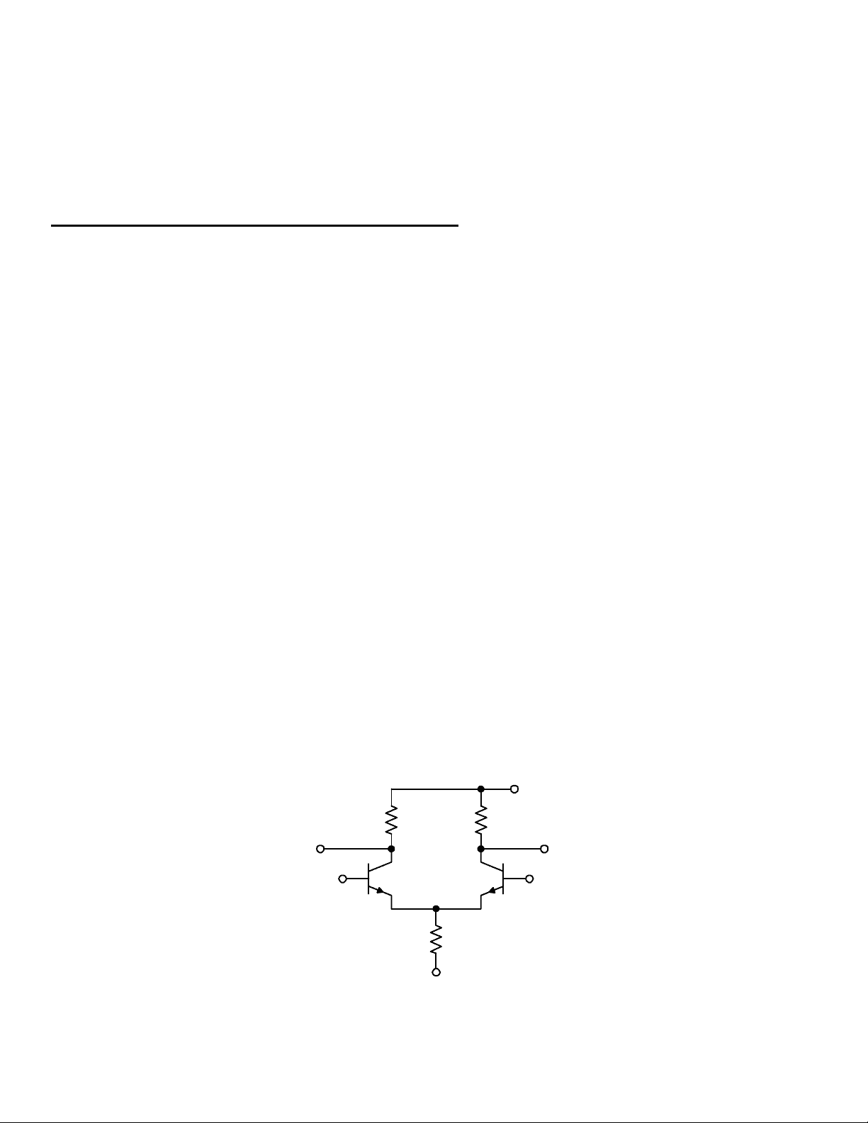
1. Assuming that the bases of Q1 and Q2 are both grounded, determine the following predicted dc voltages and
currents for the differential amplifier circuit shown in Figure 1:
VE1 = _______ VC1 = _______ IC1 = ______
VE2 = _______ VC2 = _______ IC2 = ______
2. Determine the single-ended output difference-mode gain (relative to vo1) of the circuit shown in Figure 1.
Ad (single-ended output) = ______
3. Determine the single-ended output common-mode gain (relative to vo1) of the circuit shown in Figure 1.
Acm (single-ended output) = ______
4. Determine the CMRR dB for the circuit shown in Figure 1, utilizing the results of steps 2 & 3, Part A.
CMRR dB = ______
10 k
10 k
+15 V
V
i1
V
i2
-15 V
V
o2
V
o1
100 k
Figure 1
Q1 Q2
pf3
pf4

Partial preview of the text

Download Differential Amplifier Laboratory Exercise: Predicting and Measuring Performance and more Lab Reports Electronics in PDF only on Docsity!

ECET 2310 (Electronics II) Laboratory Exercise 6

Differential Amplifier

In this investigation you will predict the dc and ac performance of a differential amplifier. During the lab session you will build a differential amplifier and measure the actual performance of your circuit. You should expect reasonable agreement between the predicted performance and the actual performance.

PROCEDURE Part A. - Preliminary Calculations:

For this part, assume that Q 1 and Q 2 are perfectly matched and have the following specifications: (Note: some of these specifications may not be needed to perform the required calculations) hFE = hfe = 500 hib = 26 mV/IE VBE = 0. 6 V hoe = 10 μS

  1. Assuming that the bases of Q 1 and Q 2 are both grounded, determine the following predicted dc voltages and currents for the differential amplifier circuit shown in Figure 1: VE1 = _______ VC1 = _______ IC1 = ______ VE2 = _______ VC2 = _______ IC2 = ______
  2. Determine the single-ended output difference-mode gain (relative to vo1) of the circuit shown in Figure 1.

Ad (single-ended output) = ______

  1. Determine the single-ended output common-mode gain (relative to vo1) of the circuit shown in Figure 1. Acm (single-ended output) = ______
  2. Determine the CMRR dB for the circuit shown in Figure 1, utilizing the results of steps 2 & 3, Part A.

CMRR dB = ______

10 kΩ 10 kΩ

+15 V

Vi1 Vi

-15 V

Vo1 Vo

100 kΩ

Figure 1

Q1 Q

Part B. - Performance of the practical differential amplifier:

  1. Build the circuit shown in Figure 1. Connect the bases of Q 1 and Q 2 to ground and measure the following dc voltages: VE1 = _______ VE2 = _______ VC1 = _______ VC2 = _______
  2. Leave the base of Q 2 connected to ground but remove the ground connection from the base of Q 1. Set vi1 = 0. 01 sin (6283t) V. In order to set vi1 to the specified amplitude a resistive voltage divider may be required between the sinewave generator and vi1. Sketch and completely label the waveforms vi1, vo1 and vo2.

t

V (^) i 0 t

V (^) o

0 t

V (^) o

0

  1. Determine the single-ended output difference-mode gain (relative to vo1) utilizing the results of step 2, Part B.

Ad (single-ended output) = ________

  1. Remove the ground connection from the base of Q 2 and instead ground the base of Q 1. Set vi2 = 0. 01 sin (6283t) V. Sketch and completely label the waveforms vi2, vo1 and vo2.

t

V (^) i 0 t

V (^) o

0 t

V (^) o

0

  1. Determine the single-ended output difference-mode gain (relative to vo1) utilizing the results of step 4, Part B.

Ad (single-ended output) = ________

  1. Remove the ground connection from the base of Q 1. Increase the amplitude of the sinewave generator in order to set vi1 = vi2 = 1. 0 sin (6283t) V. Sketch and completely label the waveforms vi1, vo1 and vo2.

t

V (^) i 0 t

V (^) o

0 t

V (^) o

0

  1. Determine the single-ended output common-mode gain (relative to vo1) utilizing the results of step 6, Part B.

Acm (single-ended output) = ______

Calculations and Results:

  1. Compare the calculated dc voltages (from step 1, Part A) and the measured dc voltages (from step 1, Part B). Describe the possible sources of error.
  2. Compare the calculated difference-mode gain (from step 2, Part A) to the measured difference-mode gains (from steps 3, 5 and 9 of Part B). Describe the possible sources of error.
  3. Compare the calculated common-mode gain (from step 3, Part A) and the measured common-mode gain (from step 7, Part B). Describe the possible sources of error.
  4. Compare the calculated CMRR dB (from step 4, Part A) and the measured CMRR dB (from step 10, Part B). Describe the possible sources of error.
  5. Determine the value of Rx in the transistor constant-current source circuit shown in Figure 3, in order that it can be used to replace the 100 kΩ resistive current source in the differential amplifier of Figure 1.

10 kΩ

1 kΩ (^) R (^) x

-15 V

Figure 3

  1. Describe the advantage(s) of replacing the 100 kΩ resistive current source with the transistor constant-current source described in Calculations and Results #5.
  2. Describe the advantage(s) and disadvantage(s) of adding equal-valued resistors in series with the emitters of Q 1 and Q 2 in the differential amplifier shown in Figure 1.

Approved by ________________________ date _________ Results due _________ Formal Report? Yes No

(rev 5/99 - WRH)