The University of Alabama in Huntsville
ECE Department
CPE/EE 422/522 01
Midterm Exam Solution
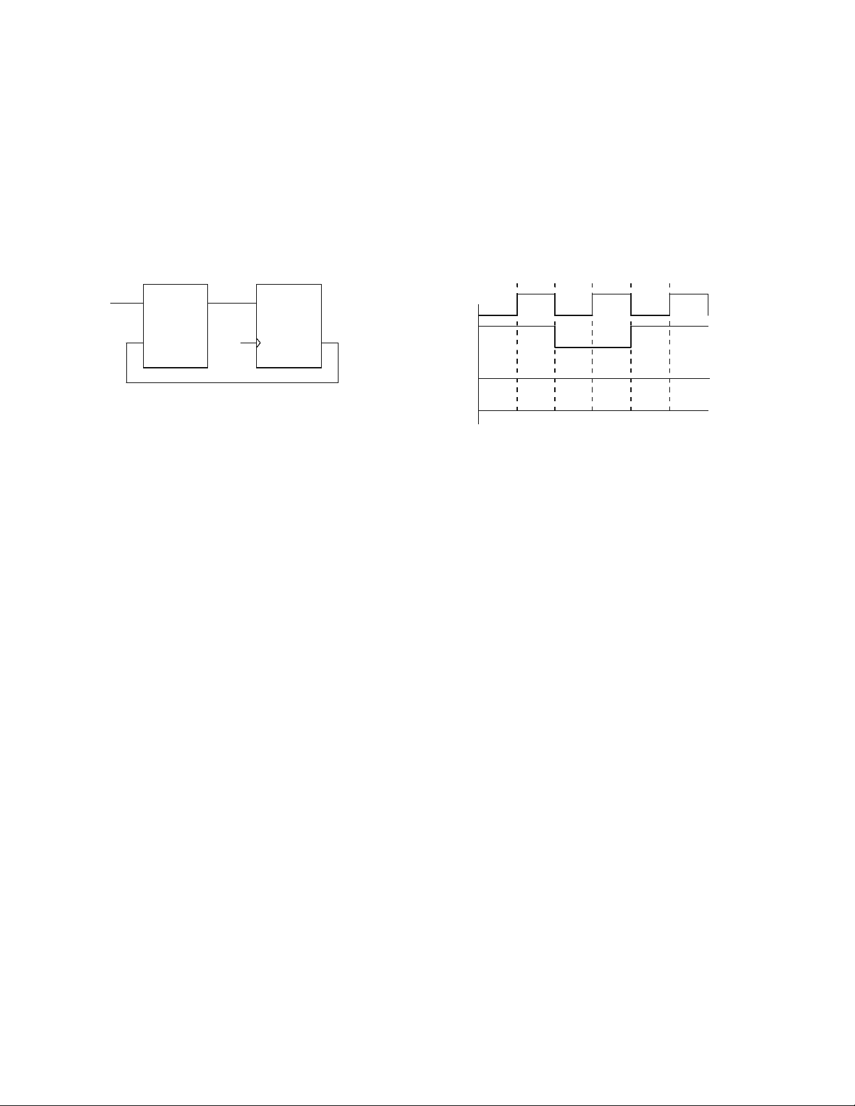
1. (10 points) A sequential network consists of a PLA and a D flip-flop, as shown. The propagation
delay for the PLA is in the range 5 to 10 ns, and the propagation delay from clock to output of the
D flip-flop is 5 to 10 ns. Assuming that X always changes at the same time as the falling edge of
the clock, what is the maximum setup and hold time specifications that the flip-flop can have and
still maintain proper operation of the network?
PLA
Clk
D
Q
Z
X
X
Clk
2
0
4
0
8
0
6
0
1
0
0
Q
Z
For both the setup time and hold time, there are two paths to consider, one from X to the D input of the
flip-flop and the other from Q to the D input of the flip-flop. From the timing diagram, tck = 40 ns, tx =
20 ns and ty = 20 ns, where tck is the clock period, tx is the time from a change on X to the active edge of
the clock and ty is the time from the active edge of the clock to a change on X. The following equations
apply: For Q: (1) tck ≥ tpdmax + tcmax + tsu, (2) th ≥ tpdmin + tcmin
For X: (3) tx ≥ tsu + tcmax, (4) th ≥ ty + tcmin
where tpd is the propagation delay through the flip-flop and tc is the propagation delay through the
combinational circuit (PLA)
So, for setup, So, for hold,
(1) 40 ns ≥ 10 ns + 10 ns + t su, tsu ≤ 20 ns (2) th ≥ 5 ns + 5 ns, th ≥ 10 ns
(3) 20 ns ≥ tsu + 10 ns , tsu ≤ 10 ns (4) th ≥ 20 ns + 5 ns, th ≥ 25 ns
For both the setup and the hold times to be always satisfied, we must take the smaller numbers so
tsu = th = 10 ns
2. (10 points) Write a short VHDL description of a 4-to-1 multiplexer using a VHDL process.
entity MUX4_1 is
port (I3, I2, I1, I0, S1,S0 : in bit;
F : out bit);
end MUX4_1;
architecture MUX4_1of MUX4_1 is
begin
process (I3, I2, I1, I0, S1, S0)
begin
if (S1 = ‘0’ and S0 = ‘0’) then
F <= I0;
elsif (S1 = ‘0’ and S0 = ‘1’) then
F <= I1;
elsif (S1 = ‘1’ and S0 = ‘0’) then
F <= I2;
else
F <= I3;
end if;
end MUX4_1;